Hello All,
Please note that I have moved all the content of this Blog over to my new Blog site:
http://najcolabs.com/
From now on I will be updating the NajCo Labs! blog. So please visit najcolabs.com & enjoy.
Thanks!
Naj
Thursday, March 26, 2009
Computer Crime & Intellectual Property Section
United States Department of Justice provides computer crime related information for public awareness on their Computer Crime and Intellectual Property Section here:
www.cybercrime.gov
www.cybercrime.gov
Monday, March 23, 2009
Monday, March 16, 2009
Time-Based ACL for ISDN Connectivity
There are 4 things to consider:
1) Define the Time-Range (under global config mode):
time-range isdn-hours
absolute start 00:00 01 January 2009
periodic weekdays 7:00 to 19:00
2) An Access List needs to be created for defining the interesting traffic & tying the Time-Range (under global config mode):
access-list 100 remark ACL for ISDN interesting traffic definition
access-list 100 deny ospf any any
access-list 100 permit ip any any time-range isdn-hours
3) Create a Dialer List with a Reference to access-list 100, as follows (under global config mode):
dialer-list 1 protocol ip list 100
4) Apply the Dialer List to the ISDN Interface (under global config mode):
interface BRI0
dialer-group 1
Tuesday, March 3, 2009
How to Upgrade IOS Image on a Cisco Router/Switch?
There are a couple of pieces to this puzzle. Here is a list of things you need to successfully perform this operation:
1) Router or a Switch you would like to upgrade
2) Console Cable
3) Straight Through Ethernet Cable (CAT5)
4) PC
5) TFTP Server (http://www.solarwinds.com/products/freetools/)
Here is a step-by-step of what needs to be done to perform the upgrade:
1) First of all, you would need to connect your Console Cable's RJ-45 end into the Router's or Switch's Console Port.
2) The other end of the Console Cable that has a DB9 Connector needs to be plugged into the Serial Port of the PC.
3) Now open up your favorite program to launch console. Or you can use Hyper-terminal (comes free with Windows). Here are a few snapshots of Hyper-Terminal settings to get you started:


4) Once you are done. You should be at a user prompt followed by a ">" sign. Now type in "enable" to get to "#" prompt also known as exec prompt.
5) Now the other important piece of the puzzle you need to focus on is running a TFTP Server on your PC. Once you have the software downloaded as mentioned above, you can then go ahead & launch it.
6) Once the TFTP Server is running on a PC. Make sure you point the path on the Server to the appropriate IOS image. Here are a few snapshots of the SolarWinds TFTP Server config:


7) Now the last piece of the puzzle is the Ethernet Connection between the Router/Switch & PC. Connect any of the available ethernet/fast-ethernet ports on your Router/Switch to your PC's Ethernet Port via a CAT5 cable. Make sure its a stright-thru cable since you are connecting two dislike devices.
8) Now assign a manual IP address on each end of the Ethernet Connection. For Example: on the PC, assign 10.10.10.1 /24 & on the Router/Switch assign 10.10.10.2 /24. Once done, try pinging either from your PC's command prompt or your Router/Switch's CLI mode via the Hyper-Terminal or any Terminal program of your choice.
9) Here is the final step: type in the following command under exec prompt:
Router#copy tftp: flash:
hit enter
Address or name of remote host []?
here you have to type in the IP address of your TFTP Server, which in this case happens to be the same as your PC's IP address.
10) Then ok all the way & the image push should start immediately.
11) Once the image is done pushing & you get a message indicating that the IOS image push was successful. Make sure you see the image on the flash. You can check this by typing in "show flash" under exec prompt.
12) And last but not least, don't forget to REBOOT. Reboot is what forces the router to initialize the new IOS image. You can reboot the Router/Switch via "reload" command under exec prompt.
Wednesday, February 25, 2009


Wednesday, February 18, 2009
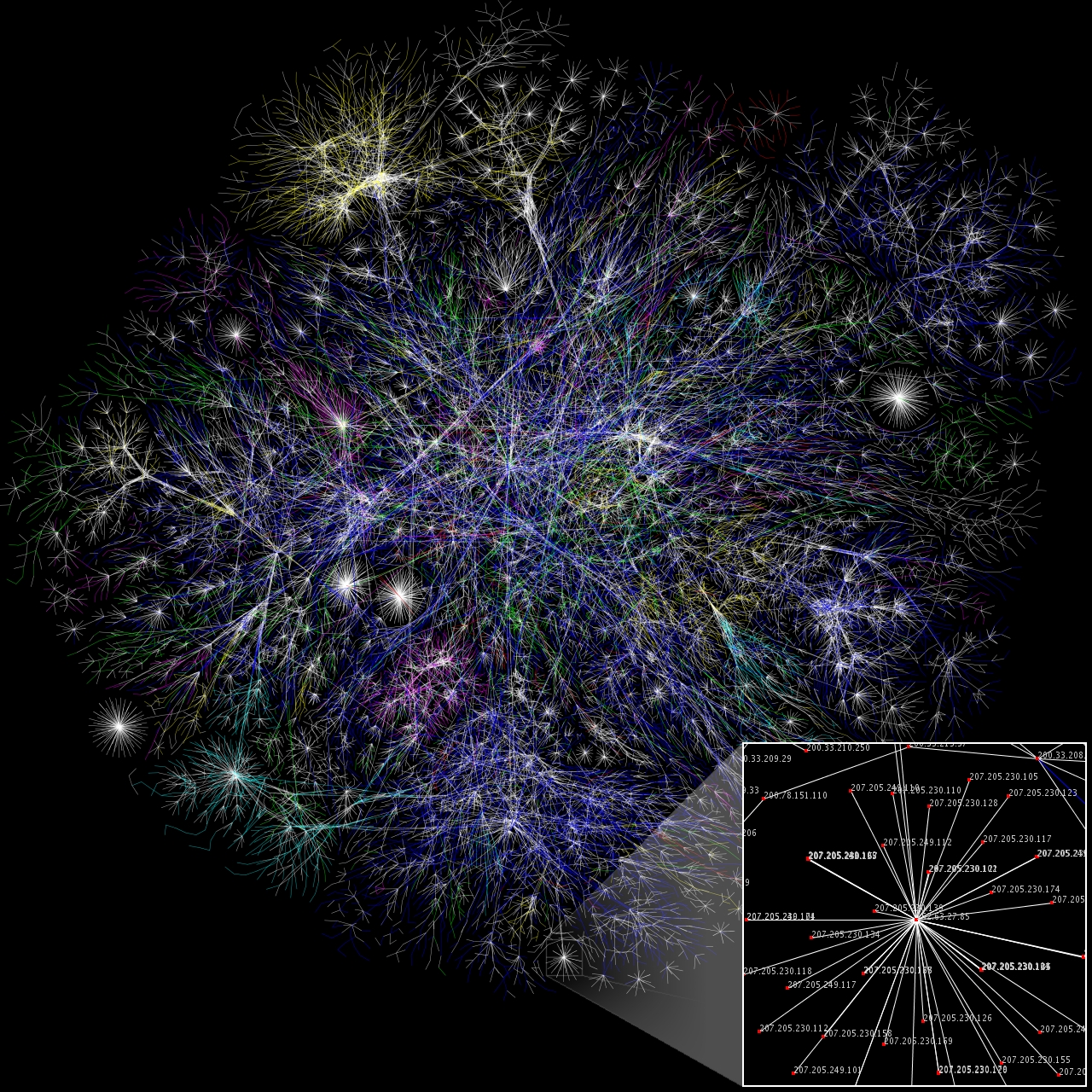
How Does an Internet Look Like?
Here is the picture of the Internet:

Visualization of the various routes through a portion of the Internet.
(Reference: http://en.wikipedia.org/wiki/Internet)
Visualization of the various routes through a portion of the Internet.
(Reference: http://en.wikipedia.org/wiki/Internet)
What is MPLS & Why is BGP required with MPLS Implementation?
FYI... The below-mentioned explanation is a very high-level overview of how MPLS & BGP work in conjunction. This post, by no means, contain detailed information regarding MPLS & BGP. If you need more information check out Cisco's site (search keyword: MPLS, BGP) & you will find tons of material with great explanations.
MPLS (Multi-Protocol Label Switching) is basically a WAN technology that allows Routing on Layer2. Now I know, this sounds crazy but just hang in there for moment & I will explain myself. Review the below-mentioned diagram while keeping the OSI Model in mind & it will give you an idea:

As you can see, MPLS is stuffed between Layer2 (Data-Link) & Layer3 (Network), therefore its considered “Layer 2.5” Protocol. Do understand the underlying WAN mechanism or infrastructure is still based of off Layer 2 technologies such as Frame Relay, ATM, PPP, HDLC, etc. MPLS essentially adds the concept of Labels, which makes it a lot quicker to deliver packets to its destination since the Layer3 lookup is not required.
Now where does BGP come into play? Why is BGP required with MPLS Implementation? These questions come to mind because with Frame Relay, ATM, PPP, HDLC we did not need a Layer3 routing protocol. Well, here is the answer:
With strictly Layer2 WAN protocols provided by the service provider or carrier, we only need Layer2 information since we (customers) need to communicate to the provider on Layer2. With MPLS however, things are a bit different. The provider now communicates via BGP. In other words, in the old days provider would only care about Layer2 stuff & the upper layers were our responsibility as far as routing. But with MPLS, the provider now participates in the Routing process & is running BGP on their router. Hence we also have to use BGP on our router for the MPLS to work.
The following WAN Designs will further clarify the above explanation:
(click on the picture to enlarge)

My Favorite Quote Ever!!!
I drew a picture of what comes to my mind when I think of this quote.
(click on the picture to enlarge)

(click on the picture to enlarge)

Monday, January 26, 2009
How do Packets Travel? What's the Force behind the Internet or WAN?
A mystery-seeking mind often wonders how does the internet work? What causes the packets to travel? What is it that pushes the packets or causes the spark, if you will?
Well the answer lies in the basics of Network Communications & the depths of Laws of Physics. Here is a scenario: you open up an internet browser & type in a URL. Here is what happens from Network/Physics perspective -->
As soon as you open the browser & type in the URL, a slue of network packets travel from your PC to the Local Area Network or LAN. Here it is piece by piece, in terms of what happens:
http://en.wikipedia.org/wiki/Sub-atomic_particle
If you grab a magnifying glass & zoom into each sub-atomic particle (like Electron) you will find out that there is something called "energy flakes or strings" that compose the Electron to define its physical characteristics. Everything in this world that physically exists on a super-microscopic level is made up of these energy strings. Here is the link for the curios:
http://en.wikipedia.org/wiki/String_theory
Good Luck!
Well the answer lies in the basics of Network Communications & the depths of Laws of Physics. Here is a scenario: you open up an internet browser & type in a URL. Here is what happens from Network/Physics perspective -->
As soon as you open the browser & type in the URL, a slue of network packets travel from your PC to the Local Area Network or LAN. Here it is piece by piece, in terms of what happens:
- Application Layer (Layer 5, 6 & 7) sends a request to Transport Layer i.e. Layer4 of the OSI Model (http://en.wikipedia.org/wiki/Osi_model)
- Layer4 creates a network socket by combining source ip, destination ip and a TCP or UDP Port # associated with the request. (http://en.wikipedia.org/wiki/Network_socket)
- Layer3 on the LAN segment gets the request from Layer4 & sends the IP information down to the LAN device (switch).
- LAN Switch grabs the info & processes the data by forwarding it to the WAN device i.e. Router (could be DSL modem, cable modem, t1 etc.)
- Router grabs the Layer3 info & forwards the request over to Layer2 device i.e. WAN device on the provider network. It could be an ATM or a Frame Relay switch.
- The provider then forwards the request to the requested host on the internet i.e. a server you are trying to access. That's the server you requested to connect to when you typed in the URL in your browser.
- The server replies back to the provider, then the provider forwards the reply back to you.
- The Router (WAN device) in your network forwards the information back based on the network socket info & eventually you get to see the site you requested.
- The information, keeping the OSI Model in mind, travels from Application Layer (Layer 5, 6 and 7) to Layer4, down to Layer3, to Layer2 & eventually Layer1.
- Layer1 deals with nothing but bits, 0's & 1's. The Binary language or the Universal language, if you will. (http://en.wikipedia.org/wiki/Binary_numeral_system)
- The information on Layer1 travels in the form of electrical signals, with a specific combination of 0's & 1's that make up a particular piece of information. (http://en.wikipedia.org/wiki/Signal_(electronics))
- If you zoom into each electrical signal you will see a stream of electrons flowing through. (http://en.wikipedia.org/wiki/Electric_current and http://en.wikipedia.org/wiki/Electron)
- These Electrons are actually the Force behind the Internet/WAN Communications.
http://en.wikipedia.org/wiki/Sub-atomic_particle
If you grab a magnifying glass & zoom into each sub-atomic particle (like Electron) you will find out that there is something called "energy flakes or strings" that compose the Electron to define its physical characteristics. Everything in this world that physically exists on a super-microscopic level is made up of these energy strings. Here is the link for the curios:
http://en.wikipedia.org/wiki/String_theory
Good Luck!
Subscribe to:
Comments (Atom)

